"Yes! It's a train set -- sort of. Unlike many railway modellers, I'm not interested in building tiny houses, or planting tiny trees. Apart from the locos my interest stops at railhead height.
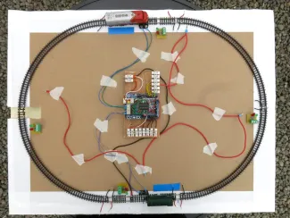
In fact, it's a very small model railway layout intended to operate two trains completely under the computer control of an Arduino. Just an oval of track with two 'stations' where the trains have to stop and four signals to control the trains' movements.
The plan is that using sensors the computer can keep tabs on where both locos are and run them between the two stations without ever bumping into each other.
We start with a train (just a loco for now) sitting at each station (The blue rectangles!). After a random time one of them sets off. If the other train hasn't moved by the time the first train gets half way to its destination a signal tells it to stop and it waits for the second train to depart before continuing into the now vacant station. Of course, the second train can drive directly to the first station because that one is now empty. And so it goes on, with the trains following each other around but never at risk of catching up.
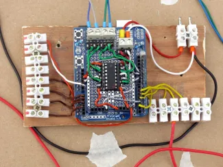
All the controlling is done by this small computer called an Arduino. It is pretty easy to control the power to the track, to make the trains accelerate or brake, but it needs to know where they are. The main tool for all this is a thing called a track circuit. You have these in 'real' railways to tell the line controller where there is a rain on the tracks so that the signals can be set accordingly to control the traffic. My set-up uses a miniature version and passes the information to the Arduino computer so that it can act as a line controller.
There are also a few sensors to tell the system when a train passes a given point and a set of signals that at least will look like that is what is controlling the trains. This is a redesign and update to a layout I had working a couple of years ago, but that had a number of drawbacks. This one should be easier to program.
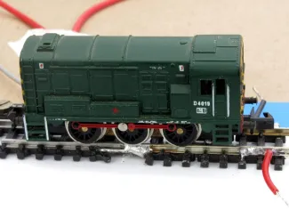
For any train buffs in the Shed, I'm modelling in 'N' gauge to allow a reasonable amount of track on a small (18"x24", or 45x60cm) baseboard that I can work with on the dining table. This loco is a bit smaller than my thumb, and neat soldering to the tracks is a bit of a challenge when you are as out of practice as me. Tim, don't giggle!
For any electronics types, I'm using a combination of control chips and some hand soldered circuits using transistors and suchlike. I'm not an electronic expert but I can (just about) follow wiring diagrams and I've had help from forums online.
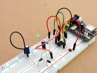
This is where I have got to so far in prototyping the track circuits. For those who understand such things, this is just the power supply part because the circuit I'm going to use needs a 12v bias voltage over and above the 12v DC voltage that powers the railway. So I'm using a 555 chip to feed a diode/capacitor voltage pump to deliver 24v (approximately).
In this area I'm only just doing better than groping in the dark because I don't have any feel for how things like transistors, diodes, resistors and capacitors work together. Basic (very basic) theory I'm OK with, but not practical application. Keeps the old grey cells busy, though.
I hope I'll have it running reliably by the time the Shed is back to normal."


